Multi-Link Operation (MLO) modes and where to verify it.
MLO is the central component of the new Wi-Fi 7 (802.11be) protocol. This new feature enables Multi-Link Devices (MLD) to establish links across multiple Wi-Fi frequency bands (2.4GHz/5GHz/6GHz) and transfer data on one or multiple links at the same time as well. This simultaneous data transmitting (Tx) and/or receiving (Rx) across multiple bands can increase total throughput by aggregating all the bandwidth. It is especially beneficial if one of the bands is congested or experiencing interference. This is ideal for real-time applications such as VR/AR/XR, 4K/8K video conferencing and streaming, which benefit from a low latency without dropping its connection. This should increase reliability and resiliency of the connection in heavyily congested areas with a lot of RF traffic in high-density environments that usually suffer from high RF utilization because of limited airtime per RF channel that can cause slower speeds and increased latency.
Devices can find a Multi-Link Information Element in Beacons and Association Requests/Responses frames. They contain the information that MLDs such as Access Points (APs) and Stations (STAs) exchange between each other to learn its MLO capabilities.
Which MLO mode is used depends on the client's hardware (MLD STAs) because they have different hardware capabilities (based on cost and application constrains) compared to the MLD APs that are required to support three MLO modes (MLSR, EMLSR, and STR). However, the MLD STAs are only required to support MLSR and either EMLSR or STR MLO modes according to the WFA certification.
Single-radio mode:
1. Multi-Link Single Radio (MLSR) - only one link is operational at a time, it is required to be supported by all MLDs (APs and STAs). The AP transmits to STA on one active link that is not in the power save mode (PM=0) as indicated by the client's MLD. Therefore, this power management signaling or power-save mode bit (PM) changes from 1 to 0 on its associated links which allows the client to quickly shift from a congested link to a less congested one if needed.
2. Enhanced Multi-Link Single Radio (EMLSR) - MLSR with link monitoring on multiple bands is required to be supported by MLDs APs but it is optional for STAs. Support for the EMLSR operation is specified in the EML capabilities field in the Basic ML element that is transmitted by the MLDs (AP and STA). All the links on the MLD (STA) are in the power save mode except the current setup link. The high capability radio on the STA could be split into two low capability radios and listen on these links simultaneously which would save power on the client's device with the benefit of the simultaneous multi-link operation on a single radio device. After the data transmission on the active link is completed, the MLD (STA) goes to the listening mode on all its EMLSR links again.
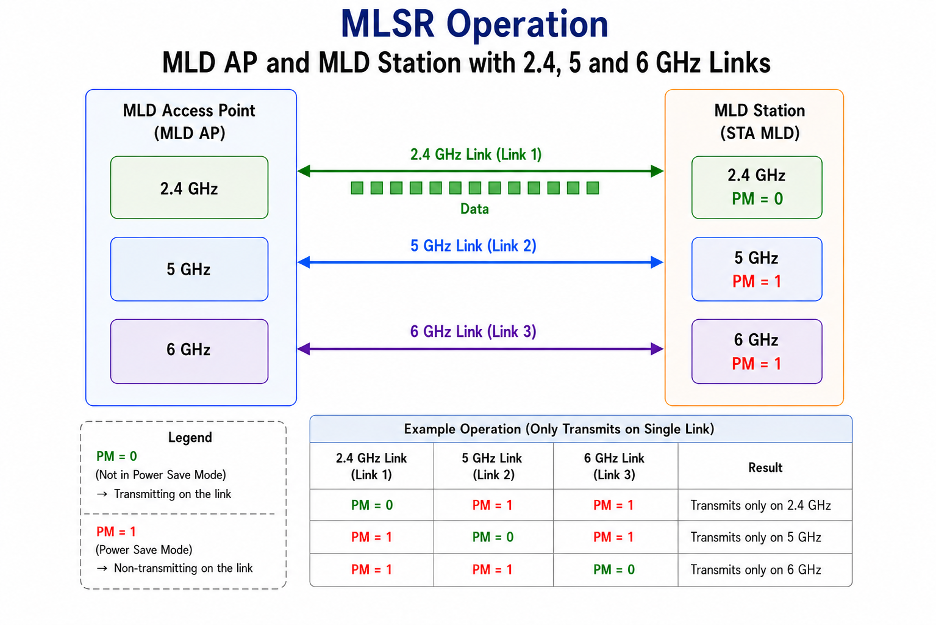 Multi-Link Single Radio (MLSR) Operation example
Multi-radio mode:
1. Simultaneous Tx and Rx (STR) - simultaneous Tx/Tx, Rx/Rx, or Tx/Rx on a pair of STR independent of each other. It is required to be supported by MLD APs but optional for the MLD STAs. In STR operation the MLD device contains multiple radios that can operate independently from each other because they have their own set of antennas. This enables the MLDs to simultaneously transmit and receive data on multiple links which delivers higher throughput, reliability, and lower latency because of the links aggregation. Because MLMR STR requires multiple radios it needs an advanced filtering to be able to deal with intra-device interference (self-interference). Therefore transmission on one band doesn't interfere into the receiver of the other band. This is important especially in 5 & 6GHz bands, where the isolation of radios is harder to achieve compare to the 2.4 & 5GHz or 2.4 & 6GHz bands. As a result, there needs to be enough physical frequency isolation between radios to allow independent operation.
2. Non-Simultaneous Tx and Rx (NSTR) - happens when cross-link self-interference occurs between two links on channels that are too close to each other because there is not enough physical frequency separation. Then the simultaneous data transmit/receive cannot be achieved and instead a pair of links are in non-simultaneous transmit/receive (NSTR) mode. These Tx/Tx and Rx/Rx operations require a precise alignment of the PPDU's (PLCP Protocol Data Unit) end time on the links that follow the ACK frame so that the PPDU transmission and reception on the links don't overlap each other. This MLO mode is more complex and its wide support in MLDs is very unlikely.
3. Enhanced Multi-Link Multi-Radio (EMLMR) - it is a MLMR (STR) with enhanced capability to adjust spatial multiplexing on multiple links. If two links operating in 5 and 6 GHz band, have 2 x 2 radios and one of the links becomes congested, then the other link can allocate its resources and reconfigure itself to operate in 4 x 4 radio mode. Even though this link can accomplish higher throughput, it will increase the complexity and overhead which can offset the advantage of EMLMR mode as a whole.
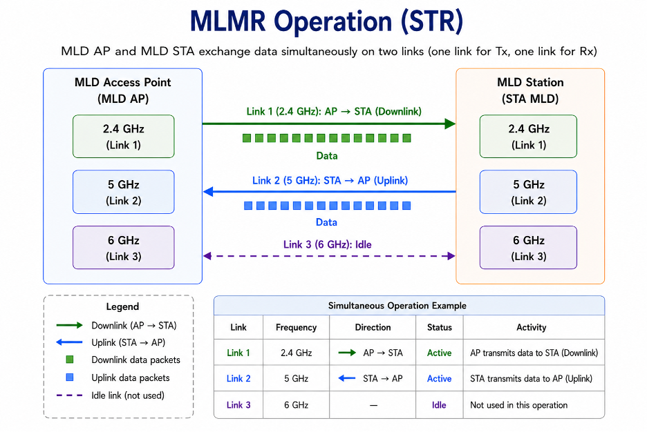 Multi-Link Multi Radio (MLMR) Operation Simultaneous Tx/Rx example
Multi-Link Reconfiguration:
For better Multi-Link Operation a dynamic reconfiguration is introduced, so the link doesn't have to be disconnected and re-associated every time to
change the links between the MLD and STA. For example, the MLD will suggest links to the STA to load balance the throughput where one setup link needs to
be removed and another added. The STA will recognize the new MLD link from the Basic ML element in the Beacons and Probe response frames of the new MLD
and can start the reconfiguration process to add the new MLD link to its setup links. In addition, the STA can add or delete links simultaneously with
its associated MLD via Reconfiguration Multi-Link element in the Link Reconfiguration Request frame.
Link Management (Disablement and Enablement):
The TTLM (TID-To-Link Mapping) is to improve the links operation by load-balancing data traffic between the STA links because the MLD has better awareness
of the transfer state than the STA that goes frequently to power save mode. The broadcasted TTLM dynamically enables or disables links of the MLD.
Multi-Link Power Management:
When the STA is in power save mode, the MLD buffers the TID traffic for this STA. The buffered data is indicated in the TIM element with AID bit corresponding
to 1 for that STA. Each station maintains its own power management state and can exchange frames if the link is in the awake state.
If the MLD STA operates in the MLO, it can be verified in Wi-Fi 7 frames. It can be found under Multilink Element and MLD Capabilities where it indicates the Maximum Number of Simultaneous Links. If this value is 0 (value + 1) it indicates that it can operate on only one link (single radio). If the value is 1 or higher (value +1) it indicates that it can operate on multiple links (multi-radio).
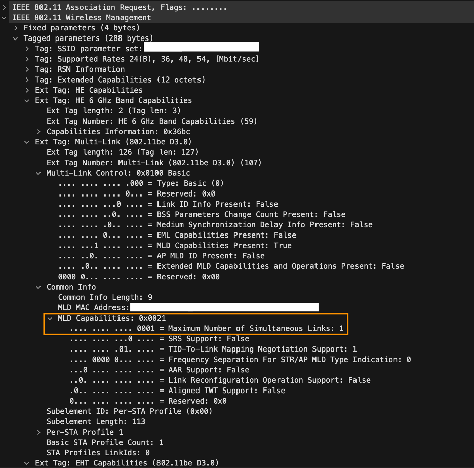 MLD STA capabilities found in Wi-Fi 7 frame
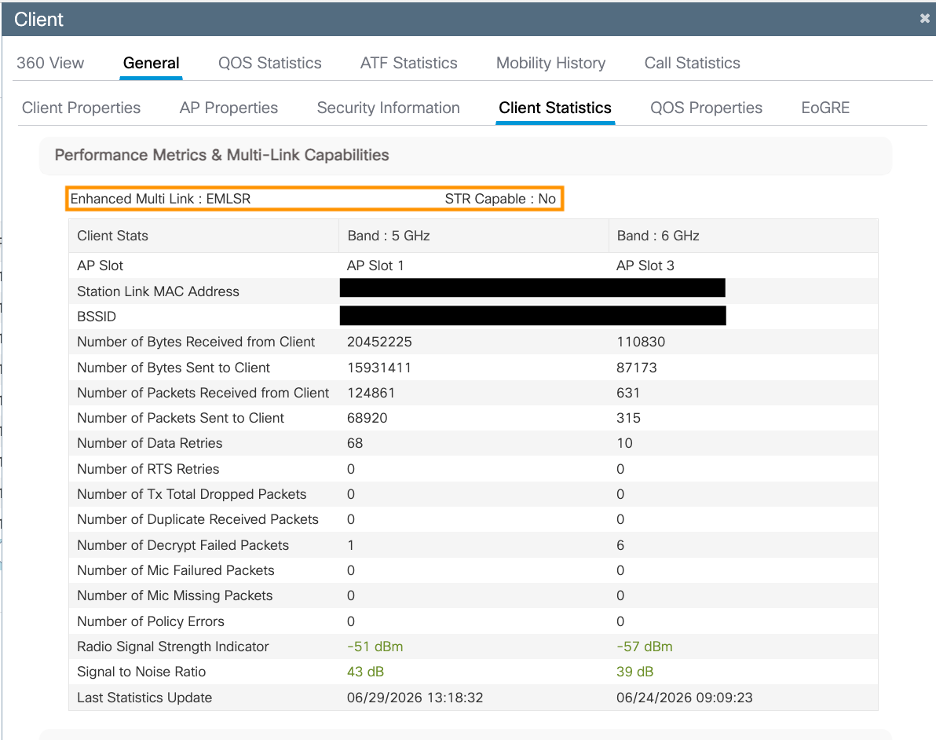 MLD STA capabilities found in Cisco WLC C9800 IOS-XE GUI under
Monitoring>Wireless>Clients>General>Client Statistics.
Resources:

Comments: